Introduction
In the previous article we found out that RTSP is the “remote control” of a video stream. We establish a connection, negotiate codecs using SDP (Session Description Protocol) and press the PLAY button.
That completes RTSP’s job, and the main work of delivering data is taken over by RTP (Real-time Transport Protocol).
RTP packs frames encoded with H.264 or H.265 into network packets and gives them sequence numbers and timestamps. Together with RTCP, it gives the receiver enough information to restore order, detect losses and align audio and video in time. RTP itself, however, does not “guarantee” anything: delivery and synchronization are provided by the application on the basis of this data. In this article I will go through how RTP works, why video needed a separate protocol, and what problems (fragmentation, jitter, desynchronization) an engineer faces when developing video capture systems (Ingest Nodes).
On accuracy. Statements about standards I checked against the RFC texts and provide links. The code in the article is assembled into a small Rust library covered by tests (21 tests): the examples are not made up “by eye”. Statements about the behavior of specific cameras are most often based on forums rather than vendor documentation, and I mark them ⚠ verify.
The history of RTP
In the early 1990s the internet was predominantly text-based: networks were designed for hypertext (HTTP), files (FTP) and mail (SMTP). The main goal was data integrity: if even one bit was lost while downloading a file, the file became useless and the download had to be repeated. So the IP + TCP stack dominated: IP handled routing, and TCP was responsible for reliable delivery.
By the mid-1990s the situation began to change:
- The first experiments with transmitting audio and video in real time appeared. For example, MBone (an experimental multicast network) and the commercial RealAudio, released in 1995.
- Personal videoconferencing was born, for example the CU-SeeMe program.
Engineers ran into the fact that existing protocols were poorly suited to transmitting media data.
Streaming video over TCP
An attempt to transmit video in real time over TCP reveals three fundamental problems that could not be solved by simple code optimization.
1. Head-of-Line Blocking
TCP delivers data to the application strictly in order. If packet #3 is lost while #4, #5 and #6 have already arrived, the OS stack will not hand them to the application. It will hold them in memory until the sender notices the loss (by timeout or by repeated acknowledgments, Duplicate ACKs) and retransmits #3.
For live video this is a problem: if the lost packet contained a piece of a keyframe (I-frame), the picture freezes for the retransmission time, which is no less than one RTT (Round Trip Time) and, on a timeout, can be noticeably longer. For networks with an RTT of hundreds of milliseconds this is already noticeable. When the packet finally arrives, the receiver gets the accumulated data in a burst.
2. Data staleness (Time-sensitivity)
In interactive systems the value of data falls quickly with time: a frame that is late is no longer needed, because a fresher one exists. The acceptable delay depends on the task (for a video conference it is fractions of a second; for surveillance and recording, different). But the principle is the same: retransmitting stale data occupies a channel that is better given to fresh data. TCP leaves no such choice: it repeats everything.
It is important not to overstate this: TCP is not “impossible” for video. HLS and DASH run over HTTP/TCP, and RTSP has an interleaved mode. But they accept higher latency (HLS — seconds and more). The problem with TCP is specifically low latency.
3. No notion of “time” at the transport level
TCP operates on a “stream of bytes”. It has sequence numbers for bytes, but no information about when those bytes were generated and when they need to be shown. With variable bitrate (VBR) encoding, heavy frames take longer to transmit and light ones less, and TCP gives the player no information on how to restore the original timeline.
An attempt to use UDP
The obvious alternative is UDP (User Datagram Protocol). It works on a “send and forget” principle: no head-of-line blocking, no acknowledgments, and the header takes only 8 bytes. If a packet is lost, the application decides what to do about it.
But sending “raw” data (for example, H.264 NAL units) straight into UDP creates new problems:
- Packet reordering. UDP does not guarantee delivery order. Packet #5 may overtake #4, for example because of routing over different paths. Without numbers, the decoder will receive data in arbitrary order, and artifacts (broken macroblocks) will appear in the picture.
- No inter-stream synchronization (Lip-Sync). Video and audio go in different streams, and UDP has no mechanism to match them.
- No frame boundaries. Networks have a limit on packet size (MTU, usually 1500 bytes for Ethernet), while a frame can weigh tens of kilobytes. It has to be cut into parts, and UDP does not tell the application where one frame ends and the next begins.
RFC 1889 and the philosophy of RTP
In January 1996, RFC 1889 “RTP: A Transport Protocol for Real-Time Applications” was published. Its authors are Henning Schulzrinne, Stephen Casner, Ron Frederick and Van Jacobson, and it was developed in the Audio-Video Transport (AVT) working group at the IETF. In 2003 it was replaced by RFC 3550, and, as the document itself says, the on-the-wire packet format did not change in the process (RFC 3550, RFC 1889).
The key idea: every packet carries metadata from which the receiver can restore order, detect losses and align time. And what to do about losses (conceal, request again, wait for a keyframe) is decided by the application.
RTP runs over UDP (although other transports are possible, including TCP inside RTSP). It is a transport-layer protocol in the sense of the RFC’s title, but, as Section 1 of RFC 3550 says, it is deliberately “incomplete”: it is a protocol framework that will often be integrated into the application itself rather than implemented as a separate layer. So I would not say that RTP sits at “the 5th or 7th OSI layer”: the standard does not describe itself that way.
+-----------------------------------+
|  Application (H.264 / AAC / Opus) |
+-----------------------------------+
|               RTP                 |  <- Adds timestamp, seq and payload type
+-----------------------------------+
|               UDP                 |  <- Speed without head-of-line blocking
+-----------------------------------+
|               IP                  |  <- Packet routing
+-----------------------------------+
RTP separates data and control into two independent streams:
- RTP (Data Channel): carries the media data split into packets with numbers and timestamps.
- RTCP (Control Protocol): a parallel stream that carries no video but conveys reception statistics (losses, jitter), sender reports for synchronization and information about the source. By default RTCP uses the next (odd) port after the RTP port, but this is only a recommendation, not a hard rule (RFC 3550, §11). The share of bandwidth for RTCP is, by recommendation, about 5% of the session bandwidth (RFC 3550, §6.2).
The structure of the RTP protocol
An RTP packet consists of a header (at least 12 bytes) and a payload.
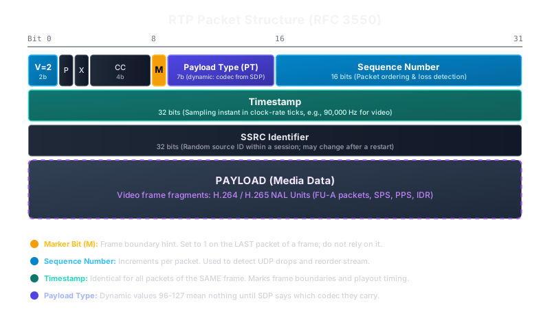
Here we are interested in four header fields:
- Sequence Number (16 bits). Increases by 1 with each packet sent. The initial value is chosen randomly, not from zero. It allows packets to be ordered and losses to be detected.
- Timestamp (32 bits). The sampling instant of the first octet of data, read from the sender’s monotonic clock rather than a system clock reading (RFC 3550, §5.1). The initial value is also random, so the absolute number means nothing: only differences matter. If a frame is split into several packets, all of its packets will have the same Timestamp.
- SSRC (32 bits). The synchronization source identifier within an RTP session. The value is chosen randomly, and if a collision is detected the source must change it. So SSRC is not a reliable “camera passport”: it may change after a stream restart.
- PT (Payload Type, 7 bits). An index of the payload format. Some values are statically assigned (for example,
0— PCMU,8— PCMA,26— JPEG), while values 96–127 are dynamic: which codec, for example,96stands for is defined by SDP (a=rtpmap:96 H264/90000) for a particular session (RFC 3551). A receiver must ignore an unknown PT.
Timestamp is measured not in milliseconds but in clock rate ticks (Clock Rate). For H.264 and H.265 video the standards require 90,000 Hz (RFC 6184, RFC 7798). Then at 30 frames per second the Timestamp step between neighboring frames is 3000 (90000 / 30), at 25 frames per second — 3600, at 29.97 — 3003. For audio the rate usually equals the sampling rate (8000 for PCMA). But the step does not have to be constant: it depends on the actual frame rate, and for reordered frames (B-frames) the Timestamp may not be ascending, even though the Sequence Number grows monotonically.
The packet header (RTP Header)
If you open a dump of an RTP packet in Wireshark, it will begin roughly like this (hex):
80 e0 1a 2b 00 2b c3 50 1f 2d 9a 00
Let us break it down field by field:
80→ convert from hex to binary: 80 (hex) -> 1000 0000 (bin). Analyze the bits:10(first 2 bits) -> Version = 2 (the current RTP version).0(3rd bit) -> Padding = 0 (no padding at the end of the packet). Padding (P) is the padding flag (1 bit). If it equals 1, padding bytes are added at the end of the packet (after the data), and the last byte of the packet indicates their count (including itself).0(4th bit) -> Extension = 0 (no header extensions). Extension (X) is the extension flag (1 bit). If X = 1, an extension is added to the base header, whose structure is defined by the profile or application. It is a reserve for the future. For example, header extensions are actively used in WebRTC, and in ONVIF streaming an extension with absolute time is used for recording playback (identifier0xABAC, ONVIF Streaming Spec §6.3).0000(last 4 bits) -> CSRC Count = 0 (no mixers, the payload follows right after the SSRC). CSRC Count (CC) is the number of Contributing Source identifiers (4 bits). If the stream comes from a single source (for example, from your camera), CC = 0.
e0→ the second byte, containing two fields at once (1110 0000 in binary):- The first bit
M=1— the Marker bit. Its meaning is set by the profile. For video under RFC 6184 and RFC 7798 it is the last packet of an access unit (that is, of a frame), soM=1means “the frame ended with this packet”, andM=0means “there are more packets in the frame”. Saying “M=0 — an intermediate frame” is imprecise: a packet can be intermediate, not a frame. - The remaining 7 bits are the Payload Type (PT):
110 0000= 96, that is, a dynamic type. Which codec stands behind it is stated in SDP. Values can be from 0 to 127. Among the static ones:- 0 → PCMU (G.711 µ-law, basic telephony audio)
- 8 → PCMA (G.711 A-law, the European telephony standard)
- 9 → G.722 (wideband audio; a historical quirk: the sampling rate is 16 kHz, while the RTP clock is declared as 8000)
- 26 → JPEG (Motion JPEG)
- 34 → H.263 (an old video codec for videoconferencing)
- H.264, H.265, VP8, VP9, Opus and much else use the dynamic range 96–127 and are defined in SDP at connection setup.
- The first bit
1a 2b→ Sequence = 6699. The end-to-end packet sequence number (uint16). From it we understand whether anything was lost and in what order to stitch the data.00 2b c3 50→ Timestamp = 2,868,048. The timestamp (uint32). At 90 kHz this is 31.87 s from a random starting point. The absolute value tells nothing; only the differences between packets have meaning. From them the receiver understands at what moment, relative to other frames, to show this one.1f 2d 9a 00→ SSRC = 523,082,240. The source identifier (uint32). It allows this stream to be told apart from others (for example, from the audio track) within the same session.
The breakdown can be verified by code (the header_from_the_article test in the accompanying library):
#[test]
fn header_from_the_article() {
    let pkt = [0x80, 0xe0, 0x1a, 0x2b, 0x00, 0x2b, 0xc3, 0x50, 0x1f, 0x2d, 0x9a, 0x00];
    let h = parse_header(&pkt).unwrap();
    assert!(h.marker);
    assert_eq!(h.payload_type, 96);
    assert_eq!(h.seq, 6699);
    assert_eq!(h.timestamp, 2_868_048);
    assert_eq!(h.ssrc, 523_082_240);
    assert_eq!(h.payload_offset, 12);
}
Sequence Number: modular arithmetic
Sequence Number is a u16, with a range of 0..65535, after which the counter returns to 0 (rollover). The rollover frequency depends on the bitrate and the packet size. At 10 Mbit/s and 1400-byte packets this is about 893 packets per second, that is, a rollover every ≈73 seconds, not “every few seconds”. At higher bitrates it happens more often, so the handling must be done correctly from the very beginning.
How to count losses correctly? You cannot write if seq != last + 1 { lost += seq - last - 1; }: this breaks on rollover and on reordering. What is needed is a signed difference modulo 2^16:
/// Signed difference `b - a` modulo 2^16: >0 — ahead, 0 — duplicate, <0 — "late".
pub fn seq_delta(a: u16, b: u16) -> i16 {
    b.wrapping_sub(a) as i16
}
The result delta = seq_delta(prev, cur) reads as follows:
delta == 1— the expected next packet.delta > 1—delta - 1packets were skipped.delta == 0— a duplicate.delta < 0— the packet is late or arrived out of order (reorder).
For statistics and jitter calculation it is convenient to expand the 16-bit seq into an extended one (extended_seq), incrementing the high bits on each rollover. The initial value is random, so you cannot assume the stream starts at zero. RFC 3550, Appendix A.1, gives a ready algorithm with three constants: MAX_DROPOUT = 3000, MAX_MISORDER = 100, MIN_SEQUENTIAL = 2 (RFC 3550, A.1). The idea is this: a small jump forward and a small lag are considered normal, while a large jump is not accepted immediately but only if the next packet continues the new sequence (most likely the source restarted). Here is its implementation in Rust:
/// Returns true if the packet is accepted (RFC 3550 A.1 `update_seq`).
pub fn update(&mut self, seq: u16) -> bool {
    let udelta = seq.wrapping_sub(self.max_seq);
    if self.probation > 0 {
        if seq == self.max_seq.wrapping_add(1) {
            self.probation -= 1;
            self.max_seq = seq;
            if self.probation == 0 {
                self.init_seq(seq);
                self.received += 1;
                return true;
            }
        } else {
            self.probation = MIN_SEQUENTIAL - 1;
            self.max_seq = seq;
        }
        return false;
    } else if udelta < MAX_DROPOUT {
        if seq < self.max_seq {
            self.cycles += SEQ_MOD; // 16-bit rollover
        }
        self.max_seq = seq;
    } else if udelta as u32 <= SEQ_MOD - MAX_MISORDER as u32 {
        // large jump
        if seq as u32 == self.bad_seq {
            // two consecutive packets after the jump — assume the source restarted
            self.init_seq(seq);
        } else {
            self.bad_seq = (seq as u32 + 1) & (SEQ_MOD - 1);
            return false;
        }
    } else {
        // duplicate or heavy reordering — accept, but do not move max_seq
    }
    self.received += 1;
    true
}
And the number of lost packets is computed like this: expected = extended_max − base_seq + 1, lost = expected − received. The tests in the library check rollover, the loss of a single packet, a jump and a small reorder.
Fragmentation (MTU) and assembling NAL units
On Ethernet the MTU is usually 1500 bytes. After subtracting the IP (20 bytes) and UDP (8 bytes) headers, 1472 bytes remain for the UDP payload. Of these, 12 bytes are taken by the RTP header, so at most 1460 bytes are available for the RTP payload, and in the case of FU-A, which has 2 more overhead bytes, 1458 remain for the data itself. In practice engineers leave a margin: tunnels and VPNs reduce the MTU, and with IPv6 the header is larger. A 4K keyframe (I-frame) can weigh hundreds of kilobytes, so one frame turns into tens and hundreds of packets.
One could send a frame as one big UDP datagram and let the IP stack cut it into fragments. But then the loss of any IP fragment means the loss of the whole datagram. So RTP payload formats cut the data at the application level: that way a loss affects one packet, not the whole datagram. RFC 6184 also notes separately that application-level fragmentation makes it possible to transmit NAL units larger than 64 KB.
For H.264 this is described in RFC 6184, for H.265 in RFC 7798.
H.264 packetization modes
The SDP parameter packetization-mode determines which packet types are allowed (RFC 6184, §6):
| Mode | Allowed packets | Comment |
|---|---|---|
| 0 (default) | Single NAL only (types 1–23) | No fragmentation and no aggregation: a NAL must fit into one packet. The receiver must support it. |
| 1 (Non-Interleaved) | single NAL, STAP-A (24), FU-A (28) | A low-latency-oriented mode. This is the one I expect to see in the SDP of most cameras (⚠ verify on your models). |
| 2 (Interleaved) | STAP-B (25), MTAP (26, 27), FU-A, FU-B (28, 29) | Allows NAL reordering in transmission. Not supported by all receivers. |
Which mode a specific camera uses is indicated in a=fmtp:... packetization-mode=.... If the parameter is absent, it is mode 0.
Small NAL units (SPS, PPS, SEI) are often combined into one STAP-A packet: [indicator, type 24][size 16 bits][NAL][size][NAL].... Large ones are cut into FU-A.
One more practical detail: RTP transmits NAL units without start codes. Decoders that expect the Annex B format (the sequences 00 00 00 01 before each NAL) require you to add start codes during assembly. And MP4 uses yet another format (a length before each NAL), so writing to a container will require one more conversion.
The anatomy of FU-A (what you parse by hand)
If the SDP codec is H.264, the parser looks right after the 12-byte RTP header (if there are no CSRCs and extensions!). The first payload byte determines the packet type (the low 5 bits):
+---------------+---------------+
| FU indicator  |   FU header   |
+---------------+---------------+
|F|NRI| Type=28 |S|E|R| Type    |
+---------------+---------------+
FU indicator(1 byte):F(1 bit) — forbidden_zero_bit (always 0).NRI(2 bits) — the importance of the NAL unit (nal_ref_idc). The value is copied from the NAL unit being fragmented, not chosen arbitrarily. For example, for frames that carry references it is usually non-zero, while for non-reference ones it may be 0.Type= 28 (5 bits) — “this is not a whole NAL, it is an FU-A fragment”.
FU header(1 byte):S=1(Start, 1 bit) — the first packet of a fragmented NAL. A signal to the parser: “allocate a buffer and start accumulating bytes”.E=1(End, 1 bit) — the last packet of this NAL.R(1 bit) — reserved, the sender must set it to 0.Type(5 bits) — the original NAL type before slicing (for example, 5 — IDR, 1 — non-IDR). The parser builds the original one-byte NAL header from theF/NRIof the indicator and theTypefrom the FU header and inserts it at the start of the assembled buffer.
The end of a NAL unit and the end of a frame are different things. E=1 means that one NAL unit has ended. A single frame (access unit) usually has several NAL units (for example, SPS, PPS, then several slices). The assembled data can be given to the decoder after each completed NAL, while the decision that the whole frame has ended is made separately. The M=1 flag on the last packet of a frame helps with this, but RFC 6184 allows the decoder to use it only as an early hint and forbids relying on it (RFC 6184, §5.1). So the condition “E=1 and M=1” is better not used as mandatory: E=1 is enough to complete a NAL, and the frame boundary should be determined by other signs (below).
FU-A assembly in Rust looks like this. Note the reconstruction of the NAL header from the F/NRI of the indicator and the Type from the FU header:
28 => {
    let fu_hdr = p[1];
    let (s, e) = (fu_hdr & 0x80 != 0, fu_hdr & 0x40 != 0);
    if s {
        // NRI and F come from the indicator, the type from the FU header
        let nal_hdr = (p[0] & 0xE0) | (fu_hdr & 0x1F);
        let mut v = vec![nal_hdr];
        v.extend_from_slice(&p[2..]);
        self.frag = Some(v);
    } else if let Some(f) = self.frag.as_mut() {
        f.extend_from_slice(&p[2..]);
    }
    if e {
        if let Some(f) = self.frag.take() {
            Self::push_nal(out, &f);
        }
    }
}
STAP-A is parsed more simply. It is a sequence of “length + NAL”:
24 => {
    // STAP-A: [indicator][size16][NAL]...
    let mut i = 1;
    while i + 2 <= p.len() {
        let n = u16::from_be_bytes([p[i], p[i + 1]]) as usize;
        i += 2;
        if i + n > p.len() {
            break;
        }
        Self::push_nal(out, &p[i..i + n]);
        i += n;
    }
}
H.265: the same ideas, different numbers
In H.265 (RFC 7798) the NAL header takes 2 bytes: F (1 bit), Type (6 bits), LayerId (6 bits), TID (3 bits). The TID value equals temporal_id + 1, so 0 is forbidden in this field, and LayerId in the base version of the standard is always 0 (RFC 7798, §1.1.4). The RTP packet types: 48 — aggregation (AP), 49 — fragmentation (FU), 50 — PACI. FU is built like this: a two-byte PayloadHdr with Type=49 (the F, LayerId and TID fields are copied from the original NAL), then one FU header byte: S, E and a 6-bit FuType (equal to the original NAL type), and then the data (RFC 7798, §4.4.3). The original NAL header is reconstructed like this:
49 => {
    if p.len() < 3 {
        return;
    }
    let fu_hdr = p[2];
    let (s, e) = (fu_hdr & 0x80 != 0, fu_hdr & 0x40 != 0);
    if s {
        // F, LayerId, TID — from PayloadHdr; Type — from FuType
        let b0 = (p[0] & 0x81) | ((fu_hdr & 0x3F) << 1);
        let mut v = vec![b0, p[1]];
        v.extend_from_slice(&p[3..]);
        self.frag = Some(v);
    } else if let Some(f) = self.frag.as_mut() {
        f.extend_from_slice(&p[3..]);
    }
    if e {
        if let Some(f) = self.frag.take() {
            Self::push_nal(out, &f);
        }
    }
}
These branches are verified by tests: the “slice — assemble” cycle returns the original bytes, and the NRI in FU-A is copied (0x65 → indicator 0x7C, 0x41 → 0x5C).
The problem of “crooked” firmware: determining frame boundaries
In an ideal world a frame is completed on M=1. But, as already said, the standard forbids relying on it, and some firmware, reportedly, does not set the flag at all (⚠ verify on your camera). So an assembler is built from the start with a forced frame-closing policy, so that it does not wait for the marker forever and does not lose memory. A frame is considered completed (and goes to the decoder or is discarded as broken) if any of the following conditions holds:
- Marker. A packet with
M=1arrived. - Timestamp change. A packet with a different RTP Timestamp arrived: all packets of one frame have the same Timestamp, so the previous frame has ended and we missed the marker. This condition is reliable only if the packets are already ordered (after the jitter buffer).
- Assembly timeout (watchdog). If, within a set time budget (for example, 30–50 ms; the value is tuned to the FPS and the network), no new packets for the current Timestamp arrived, the buffer is closed forcibly.
Jitter Buffer
RTP over UDP does not preserve packet order or uniformity of intervals and does not guarantee delivery. On Wi-Fi packets often arrive in bursts and out of order. They cannot be fed to the decoder as is, so a Jitter Buffer is used:
- It places incoming RTP packets into the buffer by
Sequence Number. - It waits a small interval (target delay). For a local network, tens of milliseconds are usually taken, and the exact value depends on the network and the acceptable latency.
- It outputs packets strictly in order.
- If a packet is late by more than the buffer window (a late packet), it is discarded so as not to increase the overall latency.
Do not confuse the two “jitters”. The jitter buffer is a data structure in your application. And interarrival jitter is a number that the receiver computes and sends to the camera in an RTCP Receiver Report. RFC 3550 (Appendix A.8) defines it as follows: transit = arrival − timestamp, d = |transit − transit_prev|, jitter += (d − jitter) / 16. The arrival time and the timestamp must be in the same units (RTP clock ticks):
/// Arrival time in RTP clock ticks (90 kHz for video).
#[derive(Default, Debug)]
pub struct Jitter {
    prev_transit: Option<i64>,
    pub value: f64,
}

impl Jitter {
    pub fn update(&mut self, arrival_ticks: u64, rtp_ts: u32) {
        let transit = arrival_ticks as i64 - rtp_ts as i64;
        if let Some(prev) = self.prev_transit {
            let d = (transit - prev).abs() as f64;
            self.value += (d - self.value) / 16.0;
        }
        self.prev_transit = Some(transit);
    }
}
The test checks two cases: with perfectly uniform delivery the estimate is zero, and with alternating “on time / 10 ms late” it converges to 900 ticks (10 ms at 90 kHz).
Audio and video synchronization (RTCP)
By itself, the RTP Timestamp is not tied to real time: each stream (video, audio) has its own random starting point and its own clock rate. The Timestamps of different streams cannot be compared directly (RFC 3550, §5.1). For audio to match video, an RTCP Sender Report (SR) is needed. In it the camera periodically reports a pair: “my current RTP Timestamp 123456 corresponds to NTP time 14:00:00.000” (plus counters of packets and bytes sent). Having received such pairs for both streams, the receiver converts them to a common time scale.
Nuances:
- The first SR does not arrive immediately. The RTCP interval is no less than 5 s, and for the first report it is half as much (2.5 s) (RFC 3550, §6.2). Until an SR arrives, audio and video cannot be precisely aligned.
RTP-Infoin thePLAYresponse gives the startingseqandrtptimeof each track (see the RTSP article). It is needed to tie the Timestamp to the start of playback, but it does not provide absolute time by itself. ONVIF goes further: it requires thePLAYresponse to include aRangewith a start in clock time andRTP-Infowithrtptime, and then the client can compute absolute time (ONVIF Streaming Spec, §5.2.1.1.2).- The camera’s time may be off. The NTP time in an SR is taken from the camera’s clock, and if it is not synchronized, the absolute value is wrong. But the relative alignment of audio and video of the same camera remains correct, because both marks were obtained from the same clock.
For multi-camera installations (VSaaS) a Wall-clock anchored scheme is often used: the node does not trust the camera’s time, records the local reception time and builds a unified timeline across all cameras at the site. The scheme has a price: reception time includes network jitter. To avoid “wobbling” the scale, one takes not a single value but the minimum of the difference arrival − rtp_time in a sliding window: queueing delays only increase it, so the minimum is closest to the “clean” offset:
/// Estimate of the arrival − rtp_time offset as the minimum over a sliding window.
/// The minimum is robust to queueing delays: they only add, never subtract.
pub struct ClockMapper {
    window: usize,
    offsets: VecDeque<i64>,
}

impl ClockMapper {
    pub fn new(window: usize) -> Self {
        Self { window, offsets: VecDeque::new() }
    }
    pub fn add(&mut self, arrival_ticks: i64, ext_rtp_ticks: i64) {
        self.offsets.push_back(arrival_ticks - ext_rtp_ticks);
        if self.offsets.len() > self.window {
            self.offsets.pop_front();
        }
    }
    pub fn offset(&self) -> Option<i64> {
        self.offsets.iter().copied().min()
    }
    /// When the frame "should" be shown (in ticks of the client's clock)
    pub fn playout(&self, ext_rtp_ticks: i64, buffer_ticks: i64) -> Option<i64> {
        self.offset().map(|o| ext_rtp_ticks + o + buffer_ticks)
    }
}
The 32-bit Timestamp must first be “unwrapped” into a 64-bit scale (otherwise the counter overflows after ~13 hours at 90 kHz). This must be done with a signed difference, so that a step backward (B-frames) is not mistaken for an overflow:
/// Unwraps the timestamp. Allows a "step back" (B-frames): the difference is signed.
#[derive(Default, Debug)]
pub struct TsUnwrapper {
    last: Option<(u32, i64)>,
}

impl TsUnwrapper {
    pub fn unwrap(&mut self, ts: u32) -> i64 {
        let ext = match self.last {
            None => ts as i64,
            Some((prev_ts, prev_ext)) => prev_ext + ts.wrapping_sub(prev_ts) as i32 as i64,
        };
        self.last = Some((ts, ext));
        ext
    }
}
Within one camera, it is better to use the NTP↔RTP pairs from SR to align audio and video, and to use wall-clock to match different cameras. This combination is what the tests verify: the offset estimate under random delays of up to 50 ms deviates by no more than 400 ticks (≈4 ms).
RTP inside RTSP (TCP Interleaved)
RTP can be transmitted not over UDP but directly inside the RTSP TCP connection, to get around NAT and firewalls. What share of streams this mode accounts for in real systems, I do not know: there are no reliable statistics, and the mode is chosen by client settings. Blocks are separated by the $ character (framing, RFC 2326, §10.12):
$ [channel: 1 byte] [length: 2 bytes, big-endian] [RTP or RTCP packet]
There is a subtlety here: over the same connection come both textual RTSP responses (for example, to keep-alive) and binary blocks with $. The parser must look at the first byte: $ (0x24) is a data block, otherwise it is the start of a text message. Because of TCP a block may arrive in parts, so you must read exactly length bytes, not “however many arrived”.
It is convenient to build the capture service (Ingest) as Transport-agnostic: the network layer extracts the RTP packet from the $ wrapper and passes it to the same place where a packet from a UDP socket would go. TCP guarantees order, so reordering is not needed in this mode, but smoothing of delivery and latency control are still needed.
SRTP and feedback (briefly)
RTP itself is not encrypted. For protection there is SRTP (RFC 3711), and ONVIF Media2 provides for SRTP and RTSPS (RFC 3711; the Media2 data is from the WSDL and the ONVIF Core specification). To request a new keyframe after losses, the RTP world has separate RTCP messages: PLI (Picture Loss Indication, RFC 4585) and FIR (Full Intra Request, RFC 5104). But whether a specific camera supports them must be checked — ⚠ verify. If it does not, what remains is to wait for the next scheduled IDR (GOP) or to reconnect.
Real cameras: problems and approaches
RTP implementations in real devices differ, and this has to be taken into account. I will not state the share of Chinese cameras in projects as fact: I have no data for such a statement. Below are four problems. Where there is a standard I refer to it, and where I rely on community reports I put ⚠ verify.
Problem 1: camera timestamp and the receiver’s clock
The camera and your server have two different clocks, and they always drift apart a little. This is normal: crystals differ by tens of ppm (parts per million). For an estimate: a 50 ppm discrepancy gives 7200 s × 50·10⁻⁶ = 0.36 s over two hours. So stories about tens of seconds of desynchronization over two hours point rather not to “crystal drift” but to an error in timestamp handling, a stream restart or a wrong clock rate. That is why I do not give specific numbers about the drift of specific SoCs: there is no confirmation.
What really happens and is worth taking into account:
- Jumps. After a reconnect, a camera reboot or a settings change, the Timestamp and SSRC may start over. You need to detect the break in the scale and re-anchor it, rather than splice “as is”.
- Irregular intervals. The real FPS can fluctuate, and the Timestamp step does not have to be even.
- B-frames. If the codec uses B-frames (the Baseline profile has none), the Timestamp in transmission order is not monotonic. The Timestamp reflects the sampling (display) instant of a frame, while the decoding order is set by the stream itself: in H.264, transmission, decoding and display are fully decoupled (RFC 6184, §1.1 and §5.1).
An approach that does not require trusting the camera’s clock is the very Wall-clock anchored from the section above: unwrap the Timestamp (TsUnwrapper), estimate the offset to your own clock as the minimum over a window (ClockMapper), and treat a break in the scale (a jump beyond what is acceptable, for example forward or backward by seconds, beyond the reordering window) as a signal to re-anchor. Note that I deliberately do not propose a formula of the form DTS = prev + clamp(ΔRTP, min, max). By limiting the step, it distorts the Timestamp and combines poorly with offset estimation. The basis here is the difference of unwrapped Timestamps plus an offset estimate, and the decision about a break is made explicitly.
Problem 2: the Marker bit
The standard says that for video M=1 is set on the last packet of a frame, but the decoder must not rely on it (RFC 6184). There are reports that some firmware leaves M=0 on all packets (⚠ verify; I could not find public confirmation for specific chips or vendors). But since the marker cannot be relied on under the standard either, there is only one solution: determine frame boundaries by three conditions (marker, Timestamp change, watchdog), as described above.
The symptom if this is not done: the assembler waits for M=1, the buffer grows, and the node drops the whole stream. So it is worth limiting the size of the assembly buffer: by volume and by time.
Problem 3: SDP and the real stream diverge
SDP describes the stream at the time of DESCRIBE. If the camera settings were changed (for example, the codec was switched in the web interface) without recreating the session, a different codec may arrive in RTP while the SDP stays the same. I did not find public confirmation of such behavior for specific models (⚠ verify), but it is not hard to protect the code regardless of the vendor: do not take the SDP on faith, check consistency.
One byte is not enough for this, and a naive check easily errs. A typical idea is to look at the bits of the first byte: & 0x1F for H.264 and (b >> 1) & 0x3F for H.265. But it has a trap: the first byte of an H.265 FU, 0x62, gives the value 2 in its low five bits, that is, a “valid” H.264 type, and a simple check confuses the codecs (this is recorded by a separate test). A working variant relies on the structural rules of the headers and on voting across several packets.
For H.265 the rules from RFC 7798 are used: F = 0, LayerId = 0, TID ≠ 0 and a type from a defined set (reserved types are discarded):
/// H.265: allowed defined types (reserved ones are discarded) + RTP packet types 48..50.
fn h265_type_defined(t: u8) -> bool {
    matches!(t, 0..=9 | 16..=21 | 32..=40 | 48..=50)
}
/// Can the payload be the start of an H.265 packet (single NAL, AP, FU)?
pub fn plausible_h265(p: &[u8]) -> bool {
    if p.len() < 3 {
        return false;
    }
    let f = p[0] >> 7;
    let typ = (p[0] >> 1) & 0x3F;
    let layer_id = ((p[0] & 1) << 5) | (p[1] >> 3);
    let tid = p[1] & 7;
    f == 0 && layer_id == 0 && tid != 0 && h265_type_defined(typ)
}
For H.264: F = 0, the expected types (data partitioning, types 2–4, practically never found in cameras), and in FU-A the R bit equals 0:
/// Can the payload be the start of an H.264 packet (single NAL, STAP-A, FU-A)?
pub fn plausible_h264(p: &[u8]) -> bool {
    if p.len() < 2 {
        return false;
    }
    if p[0] & 0x80 != 0 {
        return false; // forbidden_zero_bit
    }
    // Types 2-4 (data partitioning) practically never occur in camera streams, whereas
    // the byte 0x62 (H.265 FU, type 49) gives exactly 2 in the low 5 bits — exclude them.
    match p[0] & 0x1F {
        1 | 5..=12 | 24 => true,
        28 => p[1] & 0x20 == 0, // the R bit in the FU header must be 0
        _ => false,
    }
}
And finally, the decision is made by voting, and only if there are enough packets and one codec “passes” noticeably more often than the other:
/// Voting over a set of payloads. We decide only if one codec
/// "passes" noticeably more often than the other.
pub fn guess(payloads: &[&[u8]]) -> Guess {
    let (mut a, mut b) = (0usize, 0usize);
    for p in payloads {
        a += plausible_h264(p) as usize;
        b += plausible_h265(p) as usize;
    }
    let n = payloads.len();
    if n < 8 {
        return Guess::Unknown;
    }
    if a * 10 >= n * 9 && b * 2 < n {
        Guess::H264
    } else if b * 10 >= n * 9 && a * 2 < n {
        Guess::H265
    } else {
        Guess::Unknown
    }
}
The tests use synthetic streams (SPS/PPS in STAP-A, an IDR from FU-A and P-slices for H.264; VPS/SPS/PPS, an IDR from FU and TRAIL_R for H.265): in them the correct codec wins, and on a single packet the function honestly answers Unknown. This is a heuristic, not a guarantee. The most reliable thing is to compare the result with the SDP and ultimately parse the SPS. If the detected codec does not match the declared one, rebuild the parser and request DESCRIBE again, without counting on the stream “fixing itself”.
Problem 4: skipped packets inside FU-A
If a keyframe is cut into 100 FU-A packets, the loss of even one intermediate packet (for example, seq = 105 from a series 100..200) turns the assembled NAL unit into binary garbage: a packet with a lost part cannot be “completed”.
- Symptom. If a partially assembled NAL is passed to the decoder, the picture may “fall apart” until the next I-frame (depending on the decoder: some conceal errors better).
- Solution — Sequence Gap Invalidation. If a number is skipped between the
S=1packet and theE=1packet (delta > 1), the assembly is rejected immediately: the accumulated buffer is reset. After that the decision depends on the type of the lost NAL: the loss of a piece of an IDR or of a reference frame spoils all subsequent frames until the next IDR, so such a frame is better discarded, waiting for the next keyframe (or requesting it through PLI/FIR, if the camera supports it).
The skip check is three lines at the start of packet reception:
// packet loss: an unfinished fragment must not be used
if let Some(exp) = self.expected_seq {
    if seq != exp && self.frag.take().is_some() {
        self.dropped_fragments += 1;
    }
}
self.expected_seq = Some(seq.wrapping_add(1));
The fua_lost_packet_drops_whole_nal test checks that when the middle part of a NAL is lost, the NAL is not emitted, the drop counter increases, and the next whole NAL is assembled normally.
From RTP to MoQ: the evolution of delivery
In my Edge-First architecture, RTP is the ingest layer. After that, the Edge node assembles ready H.264/H.265 frames and sends them outward. For outward delivery I am considering MoQ (Media over QUIC): it is oriented toward low latency, and independent QUIC streams should reduce the effect of head-of-line blocking. But one must remember its status: as of 2026-10-01 it is an Internet-Draft draft-ietf-moq-transport-22, not a standard (datatracker). For today’s tasks there are more mature options (LL-HLS, WebRTC), so choosing MoQ is a deliberate bet, not the only path. I would not claim that MoQ is “free of head-of-line blocking problems”: it reduces this problem for independent streams, but it does not cancel network losses as such.
Key takeaways
- RTP is a transport, not a guarantee. It does not establish a connection: its job is to carry pieces of frames and give the receiver metadata (seq, timestamp) so that it can put them back together.
- RTP does not guarantee delivery and order. Over UDP packets are lost and shuffled, so the recovery logic falls on the depacketizer and the jitter buffer.
- Synchronization is built on Timestamp and RTCP SR. The Timestamps of different streams cannot be compared directly: NTP↔RTP pairs from the Sender Report are needed.
- Use a signed difference and an extended seq.
seq_deltaand the A.1 algorithm from RFC 3550 handle rollover, duplicates and reorder. - Fragmentation is the main difficulty. RFC 6184 and RFC 7798 must be implemented carefully: STAP-A/AP, FU-A/FU, NAL header reconstruction, adding start codes.
- Do not rely on the Marker bit. Determine frame boundaries by
M, Timestamp change and a watchdog. - Do not take the SDP on faith. Compare it with the real stream, but verify the heuristic with tests.
- Everything marked “verify” is worth reproducing on your hardware.
Sources
Standards
- RFC 3550: RTP (July 2003) and RFC 1889 (January 1996).
- RFC 3551: RTP Profile for Audio and Video.
- RFC 6184: RTP Payload Format for H.264 and RFC 7798: RTP Payload Format for H.265.
- RFC 2326: RTSP (interleaved, §10.12).
- RFC 3711: SRTP, RFC 4585 (PLI), RFC 5104 (FIR).
- ONVIF Streaming Specification v19.06 (§5.2.1.1.2, §6.3).
- Internet-Draft: Media over QUIC Transport (draft).
Code
- A Rust library with tests (
articles/rtp/examples/rtp-toolkit): header parsing,seq_delta, an A.1 seq tracker, A.8 jitter, timestamp unwrapping, clock offset estimation, H.264/H.265 assembly, codec detection. 21 tests pass (cargo test).
Related articles